Waste Tire & Plastic Pyrolysis
Continuous process flow and system description.
Continuous process flow of pyrolysis system
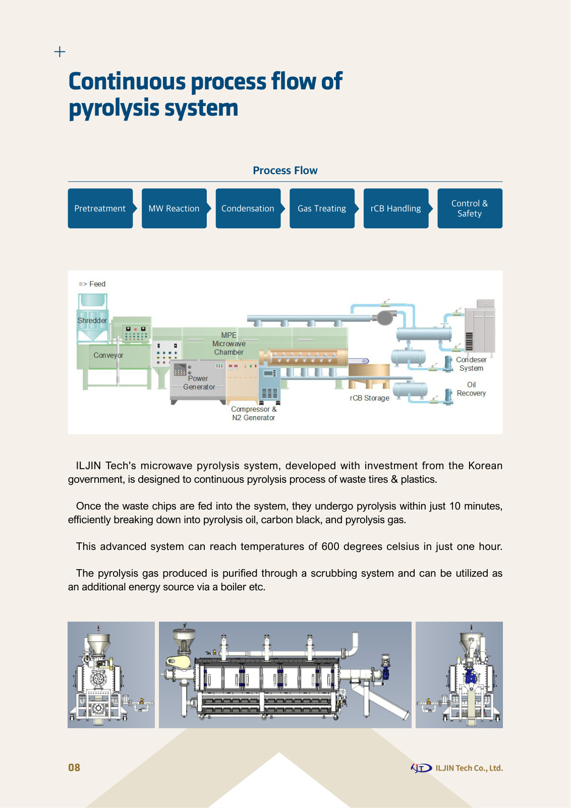
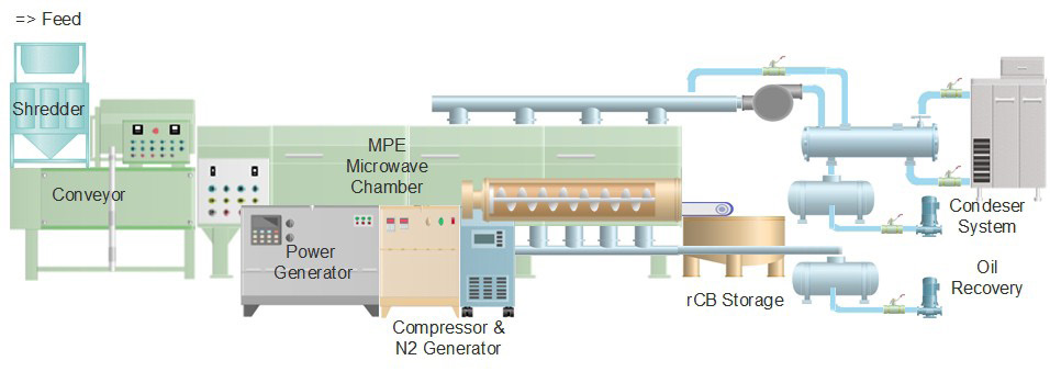
Process Flow
ILJIN Tech's microwave pyrolysis system, developed with investment from the Korean government, is designed to continuous pyrolysis process of waste tires & plastics.
Once the waste chips are fed into the system, they undergo pyrolysis within just 10 minutes, efficiently breaking down into pyrolysis oil, carbon black, and pyrolysis gas.
This advanced system can reach temperatures of 600 degrees celsius in just one hour.
The pyrolysis gas produced is purified through a scrubbing system and can be utilized as an additional energy source via a boiler etc.
Process Flow
Key modules and flow .
Continuous pyrolysis system for waste tire and plastic
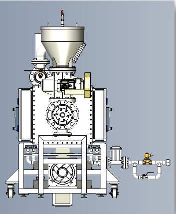
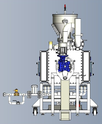
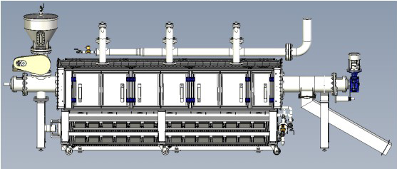
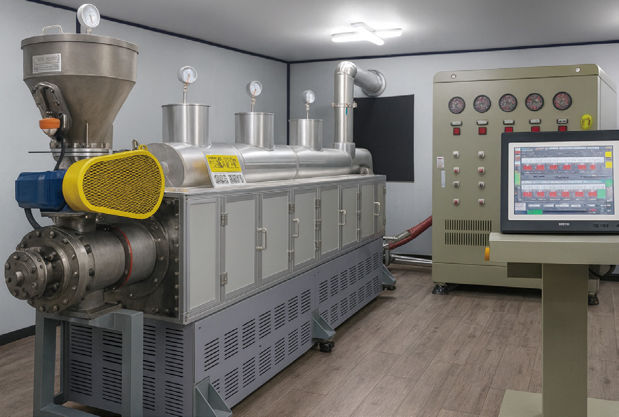
The Main Pyrolysis Reactor System is the heart of ILJIN Tech’s advanced tire and plastic recycling technology.
It utilizes a PES microwave-assisted screw type continuous reactor to thermally decom- pose waste rubber and plastics into valuable products such as pyrolysis oil, carbon black, and pyrolysis gas.
The reactor’s screw mechanism ensures uniform material transport and mixing, while the microwave energy penetrates directly into the material structure, achieving rapid and uniform heating without external combustion.
Unlike conventional rotary kiln or batch-type systems, ILJIN’s design provides precise temperature control, shorter residence time, and superior energy efficiency.
The system is fully enclosed and equipped with PES microwave system, maintaining stable operational temperatures up to 600 °C.
All process parameters—including screw speed, pressure, and temperature—are continuously monitored and controlled through an integrated PLC-HMI system, ensuring safe, automatic, and continuous operation.
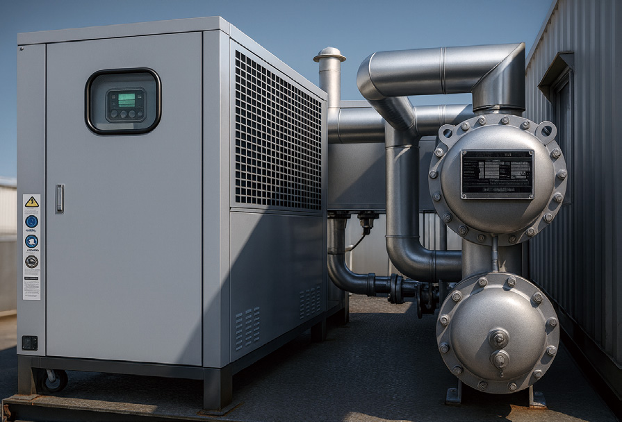
Vapor condensation system
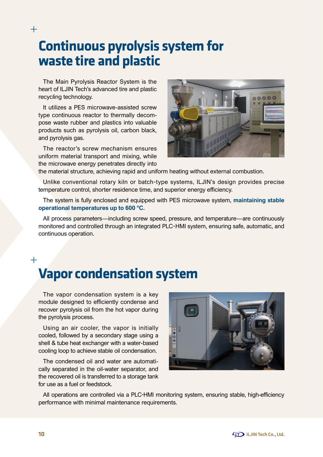
The vapor condensation system is a key module designed to efficiently condense and recover pyrolysis oil from the hot vapor during the pyrolysis process.
Using an air cooler, the vapor is initially cooled, followed by a secondary stage using a shell & tube heat exchanger with a water-based cooling loop to achieve stable oil condensation.
The condensed oil and water are automati- cally separated in the oil-water separator, and the recovered oil is transferred to a storage tank for use as a fuel or feedstock.
All operations are controlled via a PLC-HMI monitoring system, ensuring stable, high-efficiency performance with minimal maintenance requirements.
Photos & Figures